So, you’re picking out a Three Phase Armoured Cable for 2026 — and honestly, it’s not just about matching voltage and conductor size. There’s a bit more to it. The cable has to suit the load, the installation route, the fault level, and the environment it’ll be living in. A run buried under a damp service yard? That’s a whole different ballgame compared to one clipped along a warm plant-room wall. So yeah, the details really count.
With grid investments ramping up so massively, choosing the right cables has become a pretty big deal. The International Energy Agency’s 2023 report, Electricity Grids and Secure Energy Transitions, makes this clear: annual grid investment needs to hit over $600 billion by 2030—roughly double the current $300 billion. On top of that, it reckons we’ll need to add or replace more than 80 million kilometres of grid by 2040. But here’s the thing: those numbers cover all grid infrastructure, not just Armoured Cable demand. And that distinction actually matters a lot. When Fatih Birol, the IEA’s Executive Director, talked about electricity grids, he called them “the missing link in clean energy transitions.” But he’s really talking about the whole grid system here, not just the cables themselves.
Okay, so when you're actually choosing a cable that won't let you down, it comes down to a few practical things: the conductor material and cross-section, insulation, armour, sheath, operating temperature, and the installation conditions. IEC 60502-1 is a useful reference for certain extruded-insulation power cables, but you really need to check its scope and your local requirements project by project. And here's the catch: a catalogue rating can look great on paper and still be totally wrong for the real conditions on site. Honestly, you can’t just take the manufacturer’s numbers at face value. Have a qualified professional—someone who really knows their stuff—double-check the design. And here’s a detail that’s super easy to overlook: in the end, your selection is only as solid as the assumptions you’re building it on.
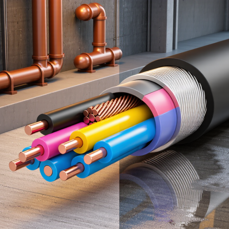
Three-phase armoured cable combines three insulated conductors with protective armour and an outer sheath. The armour helps resist impact and crushing during installation or service. Exact construction varies: steel wire, steel tape, or aluminium armour may suit different conditions. Select by voltage, load current, fault level, installation method, and exposure to moisture or chemicals. The IEA’s Electricity 2024 report projects global electricity demand will grow by an average 3.4% annually from 2024 to 2026. That growth makes reliable distribution important, but it does not replace site-specific cable calculations.
Tips: Check the cable’s installation route. A tray, buried trench, and outdoor wall have different thermal and mechanical demands. Confirm conductor size and voltage drop with a qualified electrical designer.
For a Three Phase Cable serving a motor, consider starting current and the effects of grouped cables. For buried runs, soil temperature and thermal resistivity can reduce current capacity. Confirm the cable’s rated voltage and construction against applicable standards, such as IEC 60502 where relevant. Inspect gland compatibility and bonding details before installation. A tidy cable schedule can still miss a hot, tightly packed section of tray. That deserves a second look.
A three-phase armoured cable should be selected for the place it will actually run, not just its current rating. Note whether the route is indoors, outdoors, underground, or fixed to a structure. Check for standing water, soil chemicals, oil, sunlight, and large temperature changes. Small details matter. A cable near a loading bay may face repeated knocks from carts, while one in a warm plant room may need suitable temperature-rated insulation.
Next, match the armour and outer sheath to the likely damage. Steel wire armour can provide mechanical protection, but it is not automatically right for every installation. Consider crushing, impact, vibration, and the cable’s bends and pulling route. Confirm that the armour can be correctly bonded or earthed within the installation design. Moisture protection matters too; an armoured cable is not necessarily waterproof. Read the cable’s technical data rather than relying on its appearance.
Allow room for the real installation conditions. A cable grouped tightly with others, enclosed in conduit, or exposed to heat may carry less current than expected. Check the load, run length, voltage drop, fault protection, and applicable local electrical requirements with a qualified designer or electrician. I would also verify the trench depth or support spacing before ordering. It is easy to miss. Site conditions can change, and a neat drawing may not show a sharp edge or damp corner. Recheck the route before installation.
Choosing Three Phase Armoured Cable in 2026 starts with the actual load, not a catalogue ampacity. For a balanced three-phase load, estimate current as I = P ÷ (√3 × V × power factor × efficiency). Use equipment nameplate values and include motor starting or likely future loads. Small changes matter. A pump running beside a warm boiler room may need a different cable size than the same pump in open air.
Then check current capacity against the real installation. IEC 60287 describes cable-rating calculations that account for conductor losses and heat dissipation; burial depth, soil thermal resistivity, grouping, and ambient temperature can all reduce capacity. A Three Phase Power Cable rated for one installation is not automatically suitable for another. Armour provides mechanical protection, but its construction and earthing arrangement also need review by a qualified designer.
Finally, calculate voltage drop over the full route. For a balanced circuit, use ΔV ≈ √3 × I × L × (R cosφ + X sinφ), with consistent units and cable impedance at operating temperature. IEC 60364-5-52 Annex G gives recommended limits of 3% for lighting and 5% for other uses in its stated installation context; verify local design requirements. Check the farthest outlet and motor-start conditions, not just the panel reading. I would recheck the route length on site—drawings are sometimes optimistic.
Estimated voltage drop by copper conductor size for a three-phase, 400 V supply.
Estimates assume a 100 m one-way cable length, 32 A load, 0.9 power factor, copper conductor resistance at 90°C, and 0.08 Ω/km reactance. The 3% line is a reference, not a universal requirement. Calculate design current from the load, then verify cable current capacity using the applicable installation method, temperature, grouping, and local electrical regulations. Final selection should also account for protective-device coordination and short-circuit requirements.
Choosing a three-phase armoured cable starts with the load, route, and fault conditions—not just the catalogue current rating. A 30-metre run in a warm service trench can need a different conductor size from the same load in open air. Check voltage drop, short-circuit withstand, cable grouping, and ambient temperature together. Small assumptions add up.
Copper offers higher conductivity, so it can use a smaller cross-section, but it costs more and weighs more. Aluminum is lighter and often economical, yet usually needs a larger size and carefully matched lugs. Copper costs more. That trade-off matters. For insulation, PVC suits many general-duty installations, while XLPE tolerates higher operating temperatures. Neither is automatically better: moisture, chemicals, heat, and service life should guide the choice. Confirm ratings against the cable data sheet and project design.
Armour helps resist mechanical damage, but it does not replace correct bonding, earthing, or circuit protection. Steel wire armour is common for multicore runs. Single-core AC cables need special attention because magnetic armour can heat; non-magnetic aluminium wire armour may be appropriate. A Three Phase Underground Cable may also need a suitable outer sheath and verified burial rating. Check joints, bends, and gland entry points. These are easy to overlook. I would recheck route assumptions before ordering; trench conditions can be underestimated.
| Selection factor | Option or typical construction | Practical advantages | Points to check | Common selection context |
|---|---|---|---|---|
| Conductor material | Copper | Higher electrical conductivity than aluminium for the same conductor cross-sectional area; generally compact for a given current and voltage-drop target. | Usually heavier and often more costly than an aluminium conductor of comparable electrical duty. Check conductor class, termination compatibility, and required cross-section. | Where space is limited, or where copper conductors and compatible terminations are specified. |
| Conductor material | Aluminium | Lower mass and often lower material cost than copper. Larger cross-section can be used to meet the same electrical performance requirements. | Size for current-carrying capacity and voltage drop; use terminals and installation practices suitable for aluminium, and account for joint and termination requirements. | Where reduced cable weight or material cost is important and there is sufficient space for a larger conductor. |
| Insulation | PVC | Common, cost-effective thermoplastic insulation for many power-cable applications. | Permitted conductor temperature, fire performance, chemical exposure, and installation conditions depend on the cable specification. Do not assume PVC is suitable for every environment. | General-purpose installations where the specified temperature and environmental limits are appropriate. |
| Insulation | XLPE | Thermosetting insulation commonly used where a higher permitted conductor operating temperature than conventional PVC is needed, subject to the cable standard. | Check the actual cable rating, short-circuit limit, fire and smoke requirements, and compatibility with accessories. Ratings are product- and standard-dependent. | Power distribution installations where the design benefits from XLPE insulation and its specified temperature performance. |
| Armour | Steel wire armour (SWA) | Provides mechanical protection and is widely used in multicore power cables. It can also provide a protective conductor path when designed, installed, and verified for that purpose. | Confirm earthing and bonding arrangements, fault-current capacity, gland compatibility, corrosion exposure, and the relevant cable construction standard. | Many multicore installations exposed to risk of mechanical damage, including suitable buried or industrial routes. |
| Armour | Steel tape armour (STA) | Provides a protective layer against certain mechanical impacts and is used in some cable constructions. | Its mechanical performance and intended use differ from wire armour; verify the manufacturer’s construction data and installation requirements rather than treating armour types as interchangeable. | Applications where the specified cable design uses tape armour and its protection level suits the route. |
| Armour | Aluminium wire armour (AWA) | Non-magnetic armour commonly considered for single-core AC cables, helping avoid the magnetic effects associated with a ferromagnetic steel armour around a single conductor. | Confirm the cable design, bonding method, fault protection, mechanical protection, and applicable standard with a qualified cable designer. | Some single-core AC applications; armour selection must be assessed as part of the complete circuit design. |
| Number of cores | Three-core or four-core | A three-core cable can serve three phases; a four-core design can include a neutral conductor where required. | Neutral sizing depends on the system and load, including possible harmonic currents. Protective-conductor arrangements and conductor identification must meet local rules. | Choose according to the supply arrangement, load characteristics, and earthing design—not simply the phrase “three phase.” |
| Rated voltage | For example, 0.6/1 kV cable | This is a common rated-voltage designation for many low-voltage power cables. | It is not a universal rating. Verify system voltage, cable marking, standard, and suitability for the installation before selection. | Low-voltage distribution only when the cable’s marked rating and applicable regulations match the system. |
| Conductor sizing | Selected by calculation | A suitable size can meet the circuit’s current, voltage-drop, and fault-protection requirements. | Consider installation method, ambient temperature, grouping, burial conditions, thermal resistivity, cable length, starting current, and protective-device characteristics. | Every project; use the applicable electrical design rules and verified cable data. |
| Installation environment | Indoor, outdoor, buried, or industrial route | Matching the cable construction to the route can improve service life and installation safety. | Assess water ingress, UV exposure, chemicals, corrosion, impact, bending radius, pulling tension, fire requirements, and any local restrictions on direct burial. | Before choosing insulation, sheath, armour, glands, and accessories. |
| Standards and verification | Applicable national and cable-product standards | Standards define construction, testing, marking, and performance requirements for the relevant cable type. | Requirements vary by country and application. Verify current local regulations, product certification, cable markings, and installation instructions. | At specification, procurement, installation, and inspection stages. |
Selection reminder: No single conductor, insulation, or armour type is best for every three-phase circuit. Have a qualified electrical designer determine the cable size and construction from the system voltage, load, installation route, fault level, and applicable local requirements.
For a three-phase armoured cable, begin with the rules that apply at the installation site. In 2026, check the latest adopted editions of relevant standards, not just the year printed on an old datasheet. IEC 60502-1 covers many power cables with extruded insulation, while IEC 60228 classifies conductors. Confirm that the selected voltage range and cable construction fall within the standard’s scope. Local codes may add requirements for fire performance, installation, or certification. Details matter. A certificate should identify the cable type, voltage rating, and applicable test basis. Ask for current test reports and traceable product documentation, then verify them with the issuing body where practical.
Compatibility is just as important. Match conductor size to load current, installation method, ambient temperature, grouping, and allowable voltage drop. Check short-circuit withstand, too. The armour must suit the environment, and its bonding method must work with the site’s earthing design. Confirm that glands, lugs, and termination boxes accept the cable’s actual diameter and armour construction. A common review miss is checking the cable alone, while overlooking its terminations. Do not guess. A tidy specification can still leave gaps; recheck calculations against real route conditions and the latest local requirements before purchase.
Choosing a three-phase armoured cable starts with the load, not a guess based on equipment size. Record the expected current, supply voltage, cable length, and starting demand. Then check the installation method, ambient temperature, and whether other cables will share the route. These factors affect how much current the cable can safely carry.
Three Phase Wire sizing also needs a voltage-drop check, especially on long runs. Compare the calculated result with local electrical requirements and the cable maker’s technical data. A cable that meets the current rating may still cause excessive voltage drop. Measure twice. If the load may grow, allow for realistic expansion rather than choosing an oversized cable without calculation.
Before installation, confirm the armour’s earthing and bonding arrangements, compatible glands, bend radius, and protection against moisture or impact. Check that the route avoids sharp edges and hot surfaces. Small details matter. The design should also account for fault-current protection and the conditions at each termination. An experienced electrician can verify these points on site; drawings rarely show every obstruction or change in temperature. I would not treat a catalogue table as the final answer. A careful review of the actual route can reveal details that an early estimate missed.
A reliable 3G, 4G, 5G, or 5.5G radio base station depends on stable power reaching its remote radio unit (RRU). A 600V-rated tinned copper-braided DC power cable can provide a robust connection for the RRU, which typically operates on a 48V DC supply. Its voltage rating describes the cable’s insulation capability; the system’s power supply still determines the voltage delivered. Suitable for indoor or outdoor installations, the cable is designed for communication infrastructure, where dependable power helps the RRU maintain consistent operation.
The tinned copper braid provides a conductive shield around the cable, helping reduce the effects of electromagnetic interference in electrically noisy equipment environments. This shielding can support more dependable operation alongside the station’s communication links, while the connection between the RRU and its controller is generally optical. Together, appropriately selected DC cabling and optical connectivity help keep power delivery and data transmission suited to the demands of modern radio access networks. The cable’s construction, installation conditions, and compatibility with the equipment should be considered when planning an RRU connection.
Check the route, expected load, cable length, and exposure to water, oil, sunlight, or heat. Small details matter.
No. Consider likely crushing, impacts, vibration, bends, and pulling conditions. The armour must also be bonded or earthed correctly.
No. Check the cable’s technical data for moisture protection. Its appearance can be misleading.
Start with expected current, supply voltage, run length, and starting demand. Then account for installation method and surrounding conditions. Measure twice.
A cable may meet the current rating but still have excessive voltage drop. Compare calculations with local requirements and technical data.
Yes. Grouped cables, conduit, and high temperatures can reduce safe current capacity. A warm plant room is worth checking carefully.
Check compatible glands, bend radius, earthing, fault protection, and protection from sharp edges or hot surfaces. Drawings miss things.
Allow for realistic expansion, but avoid oversizing without calculation. Recheck the actual route before ordering; I have missed small site changes before.
Choosing a Three Phase Armoured Cable in 2026 starts with understanding how its conductors, insulation, and protective armour work together, and what demands the cable must meet in its intended application. Consider the installation environment, including exposure to moisture, heat, impact, chemicals, or other site-specific conditions. These factors help determine the level of mechanical and environmental protection required.
Next, estimate the electrical load and operating current, then check that the cable’s current capacity and voltage drop are suitable for the circuit. Compare conductor materials, insulation options, and armour types in light of performance needs and installation conditions. Confirm that the selected cable meets applicable 2026 standards and certification requirements, and that it is compatible with the equipment and installation method. Finally, choose an appropriate cable size and verify practical installation details, such as routing, termination, and support, before installation.