When you're picking an Xlpe Cable for a project that spans the globe, it’s not just about choosing the one with the highest voltage rating. That’s kind of the lab view. In real installations, weak spots show up that neat test tables never reveal. Soil thermal resistivity, ambient temperature, water exposure, pulling tension, short-circuit duty, and joint quality—all of these can change performance in a big way.
Dr. George J. Anders—who wrote Rating of Electric Power Cables in Unfavorable Thermal Environment—has a pretty practical warning for us: “Cable rating depends on the installation environment, not the cable alone.” And honestly, that’s worth paying attention to. Take a 132 kV cable running through dry sand; it might need different thermal calculations than one laid in wet clay. Same goes for a 33 kV feeder inside an industrial plant—it could be dealing with oil, vibration, tight bending space, and maintenance access that’s a real pain.
So, picking the right Xlpe Cable? It really comes down to matching the project’s needs—things like voltage, conductor material, screen design, insulation level, sheath, and how it’ll be installed. Engineers will usually need to check the IEC standards (60502-2, 60840, or 62067) against whatever the purchaser put in their technical spec. And don’t forget local grid rules—they can make a difference too. The same goes for factory test records, type-test evidence, partial-discharge results, and making sure the accessories are actually compatible.
Honestly? Details are what decide reliability. A cable drum sitting in direct sunlight can end up with damage that was totally avoidable. And a joint that wasn't prepped right? It can undermine even really good insulation. It happens.
So when you're picking a sound setup, it's really a mix of things: what the manufacturer's actually done, independent testing, route data, and lifecycle cost analysis. Copper might let you shrink the conductors, while aluminium can bring the upfront cost down. But honestly, neither one is automatically the better pick. For global projects, you need documented assumptions, realistic contingency margins, and a frank look at any uncertain data. That last review is rarely perfect - but it can save you from some very costly failures.
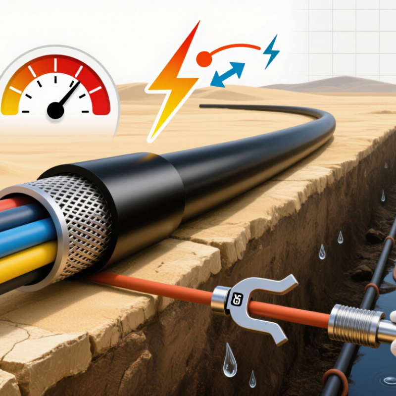
Xlpe Cable Meaning refers to cable insulated with cross-linked polyethylene. Its typical structure includes a copper or aluminum conductor, conductor screen, XLPE insulation, insulation screen, metallic screen, and outer sheath. Each layer has a job. The conductor carries current, while the screens control electric stress around the insulation. A clean, centered insulation layer matters at high voltage.
XLPE usually supports a continuous conductor temperature of 90°C and short-circuit temperatures near 250°C, subject to the applicable IEC standard and cable design. IEC 60502-1 covers many low- and medium-voltage cables, while IEC 60840 and IEC 62067 address higher voltage systems.
Do not select only by voltage. Soil thermal resistivity, duct spacing, burial depth, ambient temperature, and grouping can change ampacity sharply. I have seen a seemingly oversized cable underperform in dry backfill.
Global demand makes this discipline more important. The IEA’s Electricity 2024 report projects roughly 4% annual global electricity demand growth from 2024 to 2026. IRENA reported 473 GW of renewable capacity additions in 2023, creating more interconnection pressure. For these projects, specify moisture-resistant XLPE, longitudinal water blocking, suitable metallic screens, and a sheath matched to UV, chemicals, and mechanical stress. Verify factory tests, partial-discharge results, conductor resistance, and installation records. Standards are not interchangeable everywhere. That assumption deserves review.
For global projects in 2026, choose an Xlpe Power Cable by matching its voltage rating to the complete power system. The key values are U0, U, and Um. U0 represents conductor-to-earth voltage. U represents conductor-to-conductor voltage. Um is the highest system voltage the cable can withstand continuously. A 110 kV network, for example, may require a 64/110 kV cable, not a cable selected only by its nominal label. IEC 60840 covers cables above 30 kV up to 150 kV, while IEC 62067 addresses systems above 150 kV up to 500 kV.
Check the network design, not only the transformer nameplate. Grid grounding, fault duration, switching surges, and altitude can change the correct specification. The IEA Electricity 2024 report projects global electricity demand to grow by an average 3.4% annually through 2026. That growth increases pressure on interconnectors and renewable substations, where voltage margins can become critical. Field practice shows that engineers often focus on continuous voltage first. Emergency ratings receive less attention. That is a weakness. A cable may pass normal operation yet fail the project’s short-circuit or transient requirements. IEC 60502-1 applies to lower-voltage installations up to 3 kV, but local codes and utility specifications still require verification. One assumption can be costly. Recheck the system’s highest voltage, insulation coordination, and earthing method before approving the XLPE design.
The chart compares common power-system nominal voltages with representative XLPE cable voltage classes. Cable ratings are shown as U₀/U, where U is the rated phase-to-phase voltage and Uₘ is the maximum system voltage for the cable class. For final selection, confirm system earthing, fault duration, installation conditions, transient overvoltage requirements, and the applicable national or international standard.
Values are based on commonly used IEC voltage classes, including 0.6/1 (1.2), 3.8/6.6 (7.2), 6.35/11 (12), 8.7/15 (17.5), 12/20 (24), and 19/33 (36) kV.
How to Choose XLPE Cable for Global Projects in 2026?
Conductor sizing starts with the load, not the cable name. Record the continuous current, starting current, duty cycle, and power factor. A motor may draw six times its running current during startup. Ignore that detail, and nuisance trips can follow. For a 160 A, 400 V feeder, verify the design current against local electrical codes and the manufacturer’s tested ampacity tables. Installation method matters. Buried cables, tray cables, and cables inside ducts dissipate heat differently.
Distance changes the decision. A 250-metre feeder can pass its thermal check but still fail the voltage-drop limit. Calculate resistance using the actual conductor material, cross-sectional area, route length, and operating temperature. Include reactance for longer three-phase circuits. Keep the running drop within the project specification, often around 3% for sensitive equipment. A larger conductor may cost more initially, yet reduce motor heating and unstable operation. Short cables need less correction.
For a Cu Xlpe Pvc Cable, check the conductor’s current rating, insulation temperature, short-circuit withstand, and outer diameter. Confirm gland sizes and bending space before procurement. Grouped cables may require derating, especially in hot plant rooms. I have seen designs use a standard table without checking soil temperature or burial depth. That shortcut fails. A spreadsheet helps, but field conditions still need engineering review. Recheck the calculation when load schedules change. Small revisions can alter the conductor size. Some projects also need parallel conductors, but unequal lengths can create uneven current sharing. Measure twice.
Choosing an XLPE cable for a global project starts with the installation environment, not only voltage. XLPE insulation handles continuous operating temperatures around 90°C, but emergency limits require project-specific verification. Review conductor size, short-circuit duration, and test evidence against the applicable IEC standard. For medium-voltage systems, IEC 60502-2 may apply; higher voltages can require different specifications. A neat datasheet is not enough.
The sheath faces the real site. Direct burial demands resistance to moisture, soil chemicals, crushing, and rodents. Coastal routes add salt spray, while desert routes bring heat, dust, and sharp thermal cycles. Select sheath materials and mechanical protection accordingly. For sunlight exposure, confirm UV resistance rather than assuming it. In cold regions, check bending performance during installation. I have seen cable plans fail because minimum installation temperature was treated as a footnote.
Tips: Request test reports, installation-temperature limits, and ageing data. Compare the declared water-blocking design with the actual trench drainage plan. Ask whether the sheath survives oils, fuels, and cleaning agents. Confirm outer diameter, pulling tension, and allowable bend radius before procurement. Keep records traceable to the production batch. Also, challenge optimistic assumptions. Laboratory results may not represent rocky ground, flooded ducts, or repeated maintenance. A small field trial can reveal more than a polished specification.
| Evaluation Dimension | Typical Options or Data | Relevant Requirement or Test | Selection Guidance for Global Projects |
|---|---|---|---|
| Insulation material | Cross-linked polyethylene (XLPE), commonly specified for low-, medium-, and high-voltage power cables. | Specify the applicable voltage standard, insulation thickness, electrical type tests, routine tests, and sample tests. | Use the same cable design basis across countries only after confirming that the destination project accepts the selected IEC, regional, or utility specification. |
| Continuous conductor temperature | XLPE insulation is generally rated at 90°C maximum continuous conductor temperature when the applicable cable standard permits this rating. | Confirm the rating under IEC 60502-1 for many low-voltage designs or IEC 60502-2 for many medium-voltage designs, as applicable. | Calculate ampacity using installation method, ambient temperature, grouping, soil thermal resistivity, and conductor size; do not use the 90°C value alone. |
| Short-circuit capability | Many XLPE power-cable designs use a conductor short-circuit temperature limit of up to 250°C for a specified short-circuit duration, commonly 5 seconds. | Verify the exact limit and duration in the cable standard and calculate the adiabatic short-circuit withstand of the conductor and screen. | Check that the protective-device clearing time is compatible with the cable’s thermal withstand and that metallic screens are correctly bonded. |
| Voltage rating | Select the rated voltage according to system voltage, earthing method, fault duration, and insulation coordination; common IEC designations include U0/U. | IEC 60502-1 is widely used for power cables up to 1 kV; IEC 60502-2 covers many cables from 6 kV to 30 kV rated voltage classes. | Confirm whether the project requires IEC, BS, EN, national, utility, or North American construction and testing rules before finalizing the voltage class. |
| Sheath selection | PVC: widely used, economical, and available in flame-retardant formulations. PE or HDPE: strong moisture and abrasion resistance; flame performance must be specifically assessed. LSZH: reduced smoke and halogen-acid gas emissions when the compound and construction meet the required tests. | Assess IEC 60502 sheath requirements together with flame, smoke, halogen, oil, UV, abrasion, and mechanical tests specified by the project. | Do not treat PVC, PE, and LSZH as interchangeable. Choose the sheath based on fire risk, moisture, chemicals, mechanical exposure, and local safety rules. |
| Flame, smoke, and halogen performance | Performance depends on the complete cable construction, not only on the insulation material. LSZH formulations are intended to limit smoke and halogen-acid gas emissions. | Typical references include IEC 60332-1-2, IEC 60332-3 series, IEC 60754-1/-2, and IEC 61034-2, where required. | For tunnels, transport facilities, public buildings, and confined spaces, specify the exact flame-spread, smoke-density, and gas-emission class rather than using “fire resistant” as a general term. |
| Water and moisture resistance | Water-blocking tapes, powders, swellable components, longitudinal barriers, or metallic moisture barriers may be incorporated depending on the design. | Require the applicable longitudinal and radial water-penetration tests, especially for direct burial, wet ducts, coastal sites, and high-water-table locations. | Use a radial moisture barrier or water-blocked construction when long-term water migration could reduce insulation reliability. |
| UV and outdoor exposure | Outdoor suitability depends on sheath compound, pigment, stabilizers, cable orientation, and local solar exposure. | Request documented UV-resistance testing or project-approved material evidence; confirm compatibility with the applicable national installation rules. | For rooftops, solar farms, open cable trays, and desert sites, specify UV-resistant sheathing and verify the permitted minimum and maximum installation temperatures. |
| Chemical and hydrocarbon exposure | Resistance varies significantly by sheath compound and chemical concentration. Oils, fuels, solvents, acids, and alkalis require separate assessment. | Use project-specific chemical-immersion, oil-resistance, or compatibility tests at the expected concentration and temperature. | For refineries, chemical plants, ports, and industrial workshops, obtain a chemical exposure list before selecting PVC, PE, LSZH, elastomeric, or additional protective layers. |
| Mechanical protection | Options include unarmoured, wire-armoured, tape-armoured, or mechanically protected constructions, subject to conductor size and installation method. | Check tensile, impact, crushing, bending-radius, and armour continuity requirements in the governing standard and installation specification. | Use armour or an equivalent protection system where direct burial, rodents, impact, vibration, or high pulling forces are credible risks. |
| Installation environment | Key conditions include air or soil temperature, soil thermal resistivity, burial depth, duct fill, tray arrangement, altitude, wind, and solar loading. | Use the ampacity and correction-factor method required by the project design code; record all assumptions in the cable schedule. | A cable suitable for one country’s reference installation may require a different conductor size or sheath construction in another climate or installation arrangement. |
| Bending and pulling limits | Minimum bending radius is cable-design specific and is usually expressed as a multiple of overall diameter; pulling tension depends on conductor, armour, and pulling method. | Obtain manufacturer-approved bending radius, maximum pulling tension, sidewall pressure, and installation-temperature limits for the final cable construction. | Confirm route geometry before procurement. A technically compliant cable may still be unsuitable if the drum length, bend radius, or pulling tension is inadequate. |
| Quality and international acceptance | Require traceable raw-material records, routine-test reports, type-test evidence, dimensional checks, and conductor-resistance verification. | Align the inspection and test plan with the contract specification and the selected IEC, EN, BS, national, or utility standard. | For multi-country projects, define one controlled datasheet, test protocol, marking method, and document language before issuing purchase orders. |
| Recommended decision sequence | 1. Determine system voltage and load. 2. Define installation conditions. 3. Select XLPE insulation rating. 4. Select sheath and protection. 5. Verify environmental tests. 6. Confirm compliance documents. | The cable should pass the required electrical, thermal, mechanical, fire, water, chemical, and environmental criteria as a complete assembly. | Prioritize service life and compliance over lowest initial price, especially for inaccessible routes, offshore or coastal sites, renewable-energy plants, and critical infrastructure. |
Note: Values and test references are typical engineering guidance. The final XLPE cable design must be verified against the project specification, governing installation code, local regulations, system fault level, and the certified data for the complete cable construction.
Choosing a Cu Xlpe Cable for a global project requires more than comparing voltage and conductor size. Check the destination country’s current electrical rules before approving the design. IEC 60502-1 or IEC 60502-2 may apply to medium-voltage systems, while higher-voltage networks may require IEC 60840 or IEC 62067. Confirm the exact scope. Standards can overlap, but they are not interchangeable.
Request type-test reports, routine-test records, and recent factory inspection evidence. Verify conductor resistance, insulation thickness, partial discharge results, and sheath performance. Certification should match the cable construction, voltage class, and installation environment. I have seen projects delayed because a valid certificate covered a different cable design. A certificate alone is not enough.
Installation rules deserve equal attention. Confirm allowable pulling tension, minimum bending radius, drum orientation, and jointing procedures. Measure soil thermal resistivity instead of using a convenient assumed value. Check screen bonding, earthing, fault-current duration, and separation from other utilities. For outdoor routes, review water blocking, ultraviolet exposure, flooding, and fire requirements. Site conditions often defeat excellent calculations.
Tips: Ask the installer to mark the cable route before delivery. Photograph drum labels and test seals. Keep local engineers involved. Recheck every assumption after trench conditions change. Small oversights become expensive.
How to Choose XLPE Cable for Global Projects in 2026?
Choosing an XLPE cable for a global project starts with evidence, not catalog claims. Ask suppliers for factory locations, production capacity, and recent export references. Review certificates against the required standard, such as IEC 60502, and verify issuing laboratories. Request complete type-test reports, routine-test records, and sample serial numbers. Important gaps matter. Check conductor resistance, insulation thickness, partial discharge, sheath integrity, and fire performance where required. A signed report without traceable samples is weak evidence. Independent inspection can expose problems before shipment.
Price comparisons should use total landed cost, not only the cable price. Include conductor metal assumptions, drum costs, testing, insurance, duties, inland transport, and installation delays. Ask whether the quotation fixes copper or aluminum prices, and for how long. Clarify payment milestones and warranty terms before technical approval. The cheapest offer may become expensive. In one project review, a small unit-price saving disappeared after oversized drums required special handling. That mistake was avoidable, but the bid template encouraged it.
Delivery risk needs a visible plan. Confirm raw-material availability, approved drawings, manufacturing slots, inspection dates, and shipping routes. Require drum dimensions, weights, packing photos, and contingency dates. A port closure or failed routine test can shift installation by weeks. Use milestone updates and keep reasonable schedule float. I would still challenge my own forecast. Supplier confidence is useful, but documented performance is safer.
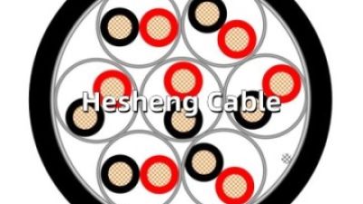
BS5308 Part 1 Type 1 300/500V PE/OS/PVC Instrumentation Cable is designed for reliable low-voltage signal transmission in industrial environments. It typically combines stranded copper conductors, polyethylene (PE) insulation, an overall screen (OS), and a durable PVC outer sheath. The PE insulation supports stable electrical performance, while the screen helps reduce electromagnetic interference that could affect measurement, control, communication, and data signals. With an unarmoured construction, the cable is practical for indoor installation where mechanical protection requirements are moderate.
This cable is suitable for industrial plants, especially in areas requiring dependable communication and data transmission between instruments, control systems, and related equipment. Its PVC sheath provides resistance to moisture and common industrial conditions, making the unarmoured version appropriate for wet indoor areas when the installation environment is properly assessed. It can also be used to connect electrical equipment in the petroleum industry, including instrumentation and monitoring systems where signal integrity is important.
When selecting the cable, consider the required conductor size, number of cores, circuit voltage, screening arrangement, installation temperature, and exposure to moisture, oil, chemicals, or mechanical impact. The unarmoured design is best suited to protected routes such as cable trays, conduits, panels, and equipment connections. Where cables may face crushing, impact, or external pulling forces, the installation should include suitable protective measures or a different construction should be evaluated.
Start with continuous current, starting current, duty cycle, and power factor. A motor may draw six times its running current during startup. Ignore that detail, and trips may follow. Recheck the design when the load schedule changes.
Yes. A long feeder may pass thermal checks but exceed the voltage-drop limit. A 250-metre route needs careful review. Calculate resistance using material, area, length, and operating temperature. Include reactance for longer three-phase circuits.
Many projects target about three percent for sensitive equipment. The exact limit depends on project requirements and local rules. A larger conductor may reduce motor heating and unstable operation. That costs more upfront, but the trade-off deserves review.
Buried cables, tray cables, and ducted cables release heat differently. Soil temperature and burial depth matter. Grouped cables may need derating, especially in hot plant rooms. A standard table can mislead.
Check current rating, insulation temperature, short-circuit withstand, and outer diameter. Confirm gland sizes and bending space before procurement. Also check drum dimensions and route access. Small omissions become expensive.
Some projects require parallel conductors for higher loads. Use equal lengths where possible. Unequal lengths can create uneven current sharing. Measure twice.
Request type-test reports, routine-test records, and recent factory inspection evidence. Verify conductor resistance and insulation thickness. Review partial-discharge results and sheath performance. A certificate alone is not enough.
Check pulling tension, bending radius, drum orientation, and jointing procedures. Measure soil thermal resistivity instead of guessing. Review earthing, screen bonding, fault duration, and utility separation. Flooding, sunlight, water, and fire conditions may change the design.
Ask installers to mark the route before delivery. Photograph drum labels and test seals. Keep local engineers involved. Recheck every assumption after trench conditions change. The spreadsheet helps, but field conditions still decide.
Choosing the right Xlpe Cable for global projects in 2026 requires a structured evaluation of both technical performance and project conditions. Start by understanding the cable’s conductor, insulation, shielding, and outer sheath, then match its voltage rating with the power system’s operating voltage and fault requirements. Conductor size should be calculated according to load current, transmission distance, allowable voltage drop, short-circuit performance, and future capacity needs.
Environmental conditions are equally important. Assess resistance to heat, moisture, chemicals, sunlight, mechanical stress, and fire according to the installation location. Confirm that the cable meets applicable international standards, certification requirements, testing procedures, and local installation rules. Finally, compare suppliers based on manufacturing capability, routine and type-test records, material consistency, total cost, production schedules, logistics, and delivery reliability. A balanced decision should consider long-term safety, maintenance requirements, energy efficiency, and project risk rather than focusing only on the initial purchase price.